How to install the 2N IP Style Door Intercom
This Step-by-Step guide leads you through the simple, innovative installation process for the flagship 2N IP Style smart door intercom.
How to correctly install the 2N IP Style
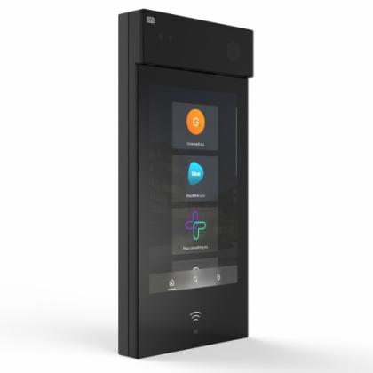
There are two mounting options for the 2N IP Style - it can be easily installed in either surface or flush-mount format, dependent upon the location and wall material the door intercom device will be located upon.
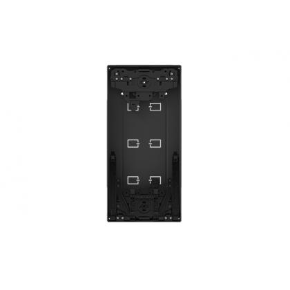
When purchasing a 2N IP Style device, you will also need to order either a surface-mount back box (Part Number 9157002) or flush-mount back box (Part Number 9157001)
.jpg)
Surface mounting the IP Style intercom unit is the simplest and quickest installation format (needing no cut-outs in the wall) and requires only half of the same steps as the flush installation.
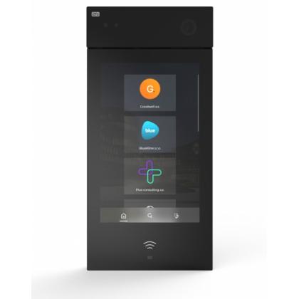
Flush installation
.jpg)
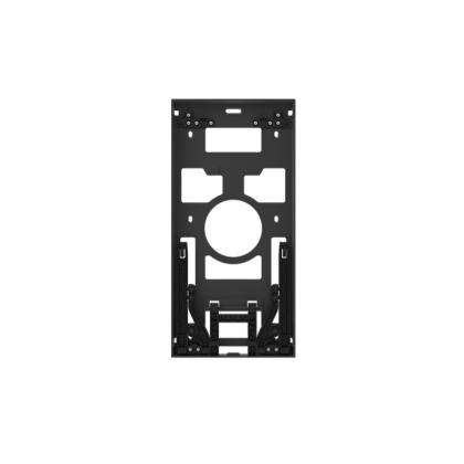
For flush installation, you need a flush mount box (9157001) in addition to the intercom unit itself. The basic step instructions on how to install are on the lids of the product boxes; however it is recommended to open the installation manual on 2N's 'our wiki' page.
Steps to install 2N IP Style:
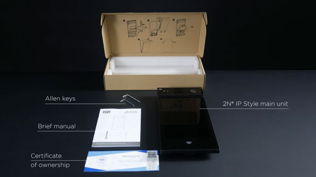
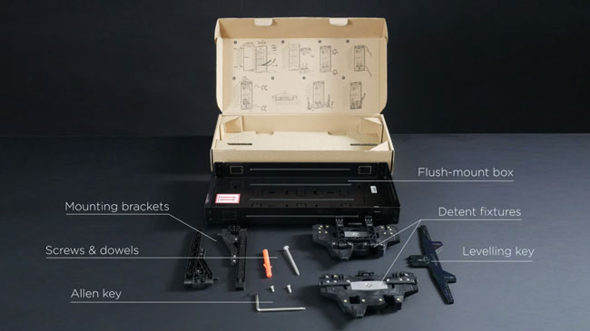
1. Check what's inside the flush mount back box carton and the IP Style packaging.
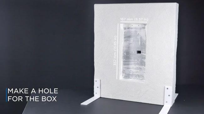
2. Cut a recess in the wall for the flush mount box, using the provided template/cut-out dimensions.
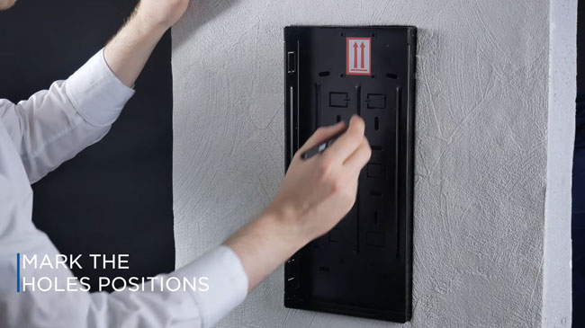
3. Check the flush mount back box is oriented correctly and mark the fixing hole positions.
4. Prepare dowels and make a hole for the cabling where suitable.
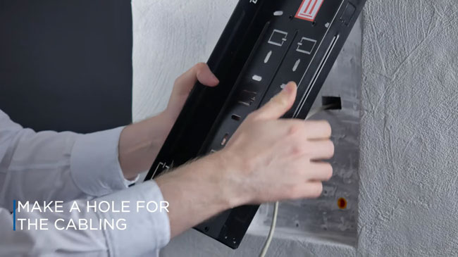
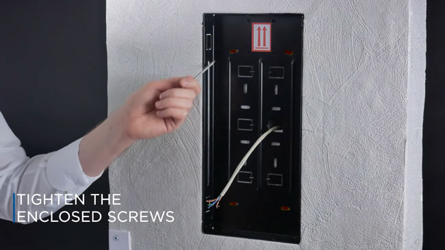
5. Pull the cable through and anchor the box using appropriate fixing screws. Tighten the enclosed screws.
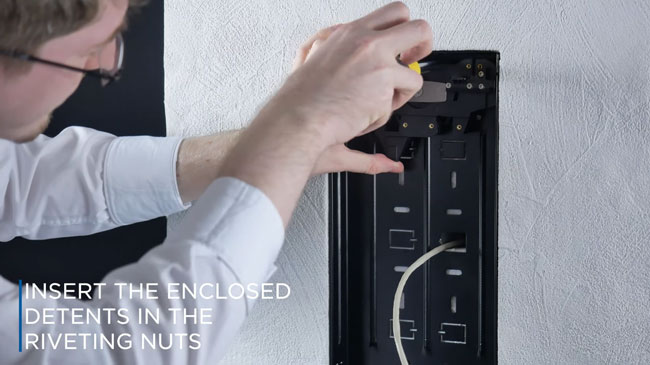
6. Insert the enclosed detents in the riveting nuts and fit it with screws. Do the same for the bottom detent.
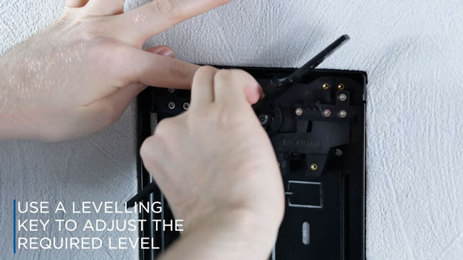
7. Use a levelling key to check the height of the detent embedding to make sure the key is aligned with the mounting box edge and the detent surface. If the detent seems too deep untighten the screws to remove the tent fixture.
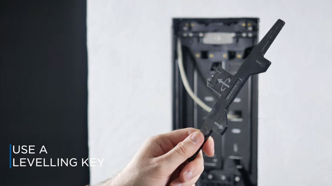
8. Insert a levelling key in the levelling mechanism grooves and turn it to adjust the required level. After levelling, re-anchor the fixture with a screw and do the same for the bottom detent if needed.
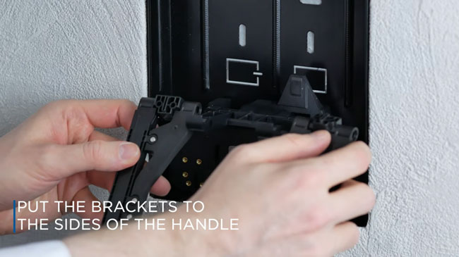
9. Place the brackets to the left and right sides of the bottom detent handle and fit their positions using screws. (The mounting box installation is now complete).
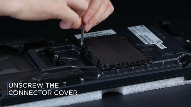
10. Now unscrew the connector cover on the back of the IP Style device.
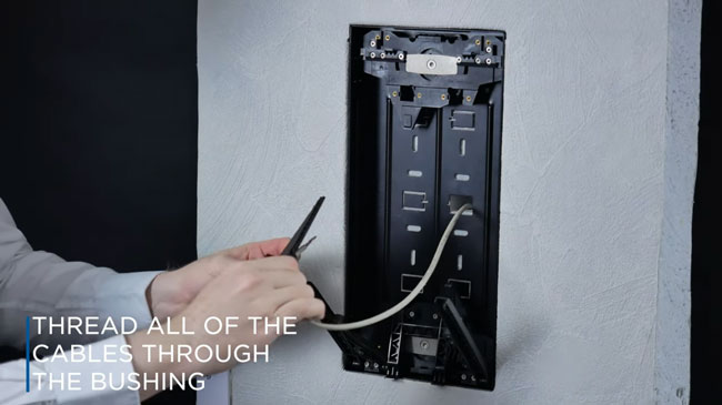
11. Thread all of the unterminated cables through the bushing on the inside of the connector cover.
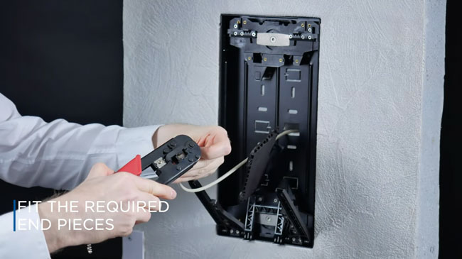
12. Fit the required terminations/connectors.
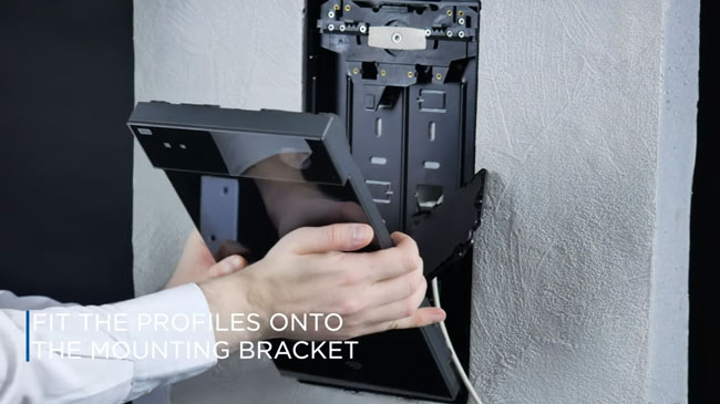
13. Fit the profiles of the IP Style device back onto the mounting bracket and slide them down to the lowest possible position anchoring the device by snapping it into place.
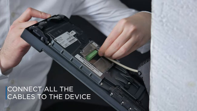
14. Connect all the cables to the Style intercom device and screw the connector cover back on.
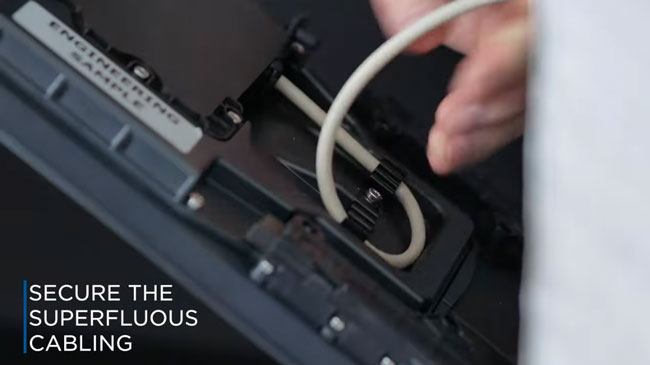
15. The mounting bracket provides sufficient support for cable installation, so it's unnecessary to support the device in any way. Secure any extra cabling in the clips.
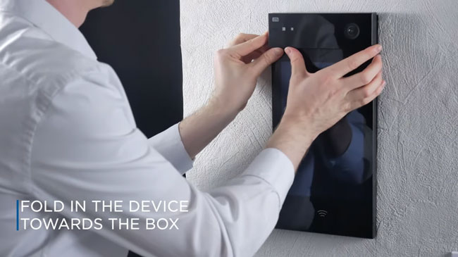
16. Fold in the device towards the flush mounting box and press downwards to seal the installation.
17. Lock the position by tightening the two screws inside the device using the allen key.
Also read:
Deep dive look at the 2N IP Style smart door intercom
2N IP Style now with QR Code access control
2N WaveKey to revolutionise Mobile Access
What is a Contactless Pathway?
Access Control Contactless Authentication Methods
How to design an Access Control System
Need help designing or specifying a contactless access control system? |